Rigbits User Documentation
Rigging tools
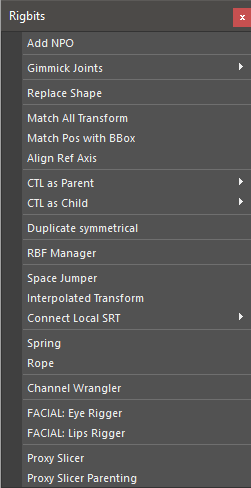
Add NPO
Add a transform as parent of each selected object in order to neutralize the local values to the reset position
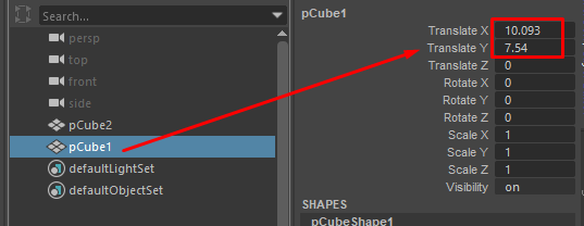
The tranlate X and Y have some values
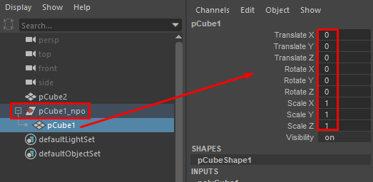
All the local transform values are reset
Gimmick Joints
Rigbits > Gimmick Joints opens a window to add helper joints for deformation, mirror them to the other side, and save them to a file.

Gimmick joints don’t need a built Shifter rig. When the joints belong to a Shifter rig, the rig’s joint naming rules are used to find the side of each joint, so custom side names work. Otherwise the usual side tokens are used (L0_, _L_, _L and the right side ones).
All the new joints are added to the rig_deformers_grp set, which is created if it doesn’t exist.
Create
Add Joint: Adds a deformer joint driven by each selected object. The joint is parented under
jnt_orgif it exists, otherwise under the object.Add Blended Joint: Adds a
blend_<joint>joint for each selected joint. The blended joint follows the joint’s translation and a part of its rotation, set with the Blend value (0.5 rotates it half way). It is placed under the joint’s parent.
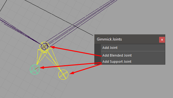
Add Support Joint: Adds a
blendSupport_<index>_<joint>joint under each selected blended joint. Support joints help with deformation and are usually driven later with SDK or RBF.
Mirror
Mirrors the blended joints, and their support joints, from Left to Right or from Right to Left. With nothing selected, all the gimmick joints of the side are mirrored; otherwise only the selected ones. Each mirrored blended joint is created for the mirrored joint with the same blend value, and each support joint keeps its index and gets the mirrored position and orientation. Mirrored joints that already exist are kept, unless Replace is on.
Flip Support Orientation
Adds 180 degrees to the joint orient of the selected support joints on X, Y or Z.
Select / Delete
Selects or deletes the gimmick joints of the checked sides. Deleting a blended joint also deletes its support joints and its pairBlend node.
Import and Export
The File menu imports and exports gimmick joints to a .gst file: all of them, or only the selected ones (with the support joints of the selected blended joints). Import rebuilds the blended joints on their source joints and then the support joints, and skips the ones whose joint is missing in the scene.
With mGear file drop enabled (see File Drop), dragging a .gst file into Maya’s viewport imports it.
Note
Blended and support joints made by older mGear versions are recognised by the tool and can be mirrored, selected and exported. The Rigbits commands rigbits.addBlendedJoint() and rigbits.addSupportJoint() keep working in custom steps and create the same joints as the window.
Shifter Custom Step
To rebuild the gimmick joints with the rig, export them to a .gst file, then create a post custom step from the Import Gimmick Joints Configuration template (see Custom Step Templates) and set its options in setup():
self.gimmick_path: the.gstfile. Leave it asNoneto pick the file when the step runs.self.replace: delete gimmick joints with the same names before rebuilding them.
The step can also be written by hand. A minimal post custom step:
import mgear.shifter.custom_step as cstp
from mgear.rigbits.gimmick_tool import core


class CustomShifterStep(cstp.customShifterMainStep):
    def setup(self):
        self.name = "gimmick_joints"

    def run(self):
        core.import_file("C:/rig/data/hero.gst")
To create the joints in code instead of from a file, use the Rigbits functions or the gimmick core:
from maya import cmds

import mgear.shifter.custom_step as cstp
from mgear.rigbits.gimmick_tool import core


class CustomShifterStep(cstp.customShifterMainStep):
    def setup(self):
        self.name = "elbow_gimmicks"

    def run(self):
        for side in ("L", "R"):
            blend = core.create_blend_joint("arm_{}0_1_jnt".format(side), blend=0.5)
            support = core.create_support_joint(blend)
            cmds.setAttr(support + ".translateY", 1.0)
File Format
.gst files are JSON. The type key is "gimmick_joints" and the joints list holds the blended joints (source joint, blend value, comp scale, radius and color) and then the support joints (blended joint, local translate, rotate, joint orient, scale, rotate order, radius and color). Files exported by the old Gimmick Setup Tool can also be imported.
Scripting Access
from mgear.rigbits.gimmick_tool import core

# Create
blend = core.create_blend_joint("arm_L0_1_jnt", blend=0.5)
support = core.create_support_joint(blend)

# Find
core.list_gimmick_joints()                            # all
core.list_gimmick_joints(kind=core.BLEND, side=core.LEFT)
core.get_source_joint(blend)                          # "arm_L0_1_jnt"

# Mirror all the Left gimmick joints to the Right side
core.mirror_gimmick_joints(direction=core.LEFT_TO_RIGHT)

# Export and import
core.export_file("C:/rig/data/hero.gst")
core.import_file("C:/rig/data/hero.gst", replace=True)

# Open the window
from mgear.rigbits.gimmick_tool import ui
ui.show()
Replace Shape
Replace the shape of one object shape with another
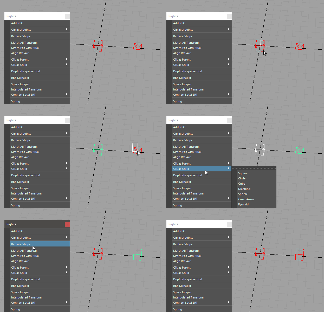
Match All Transform
Align one object to another object using the world Matrix reference.
Match Pos with BBox
Center the position of an object in the center of the bounding box of an object.
Align Ref Axis
Create a reference locator axis based on a point selection. This command needs at less 3 points.
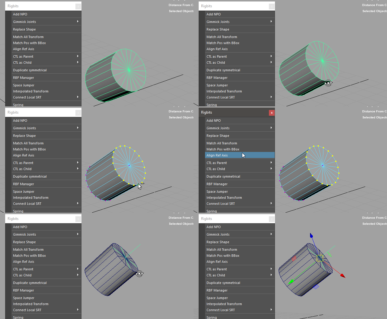
Tip
Very useful to find rotation axis in mechanical rigs if the transformations of the mesh have been freeze.
CTL as Parent
Create a control of the selected shape as parent of each selected object.
Ctl as Child
Create a control of the selected shape as child of each selected object.
Duplicate Symmetrical
Duplicate and mirror the selected object and his children. This is done by negating some axis scaling and inverting some of the values. This will provide a mirror behavior. Also handle some renaming. i.e: from _L to _R
RBF Manager
A tool to manage a number of RBF type nodes under a user defined setup(name)
2.1 quick overview
RBF Manager Tutorial
- Steps -
set Driver set Control for driver(optional, recommended) select attributes to driver RBF nodes Select Node to be driven in scene(Animation control, transform) Name newly created setup select attributes to be driven by the setup add any additional driven nodes position driver(via the control) position the driven node(s) select add pose
Add notes - Please ensure the driver node is NOT in the same position more than once. This will cause the RBFNode to fail while calculating. This can be fixed by deleting any two poses with the same input values.
Edit Notes - Edit a pose by selecting “pose #” in the table. (which recalls recorded pose) reposition any controls involved in the setup select “Edit Pose”
Delete notes - select desired “pose #” select “Delete Pose”
Mirror notes - setups/Controls will succefully mirror if they have had their inverseAttrs configured previously.
Space Manager
Create and manage space switches for rig controls. Space switches allow controls to follow different parent spaces (world, local, custom targets).
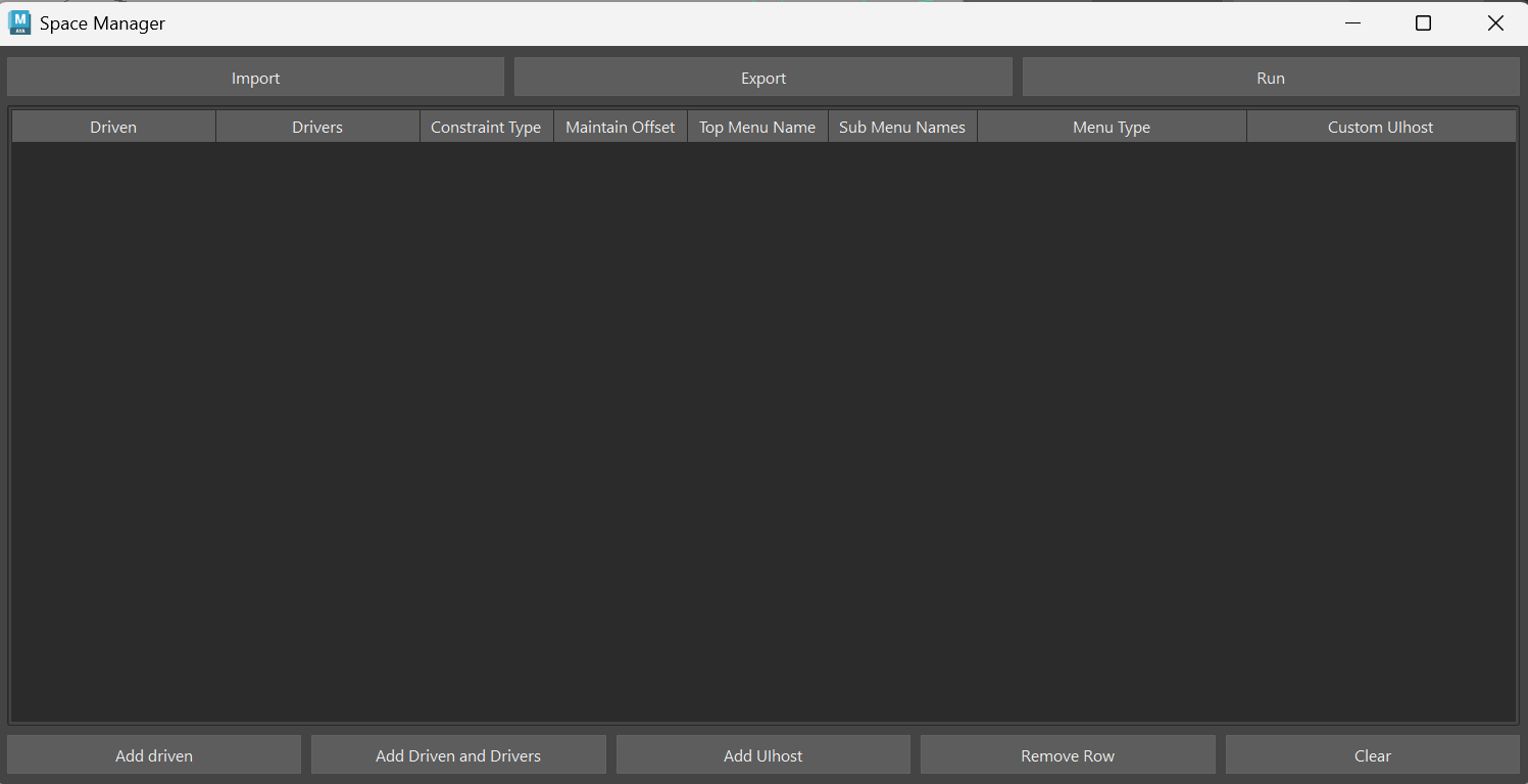
Constraint Types:
Parent - Full transform constraint (position, rotation, scale)
Point - Position only constraint
Orient - Rotation only constraint
Scale - Scale only constraint
Menu Types:
Enumerated - Dropdown attribute for discrete space selection
Float - Blend attribute for smooth space interpolation
Workflow:
Select the control that needs space switching
Add target spaces (objects to follow)
Choose constraint type and menu type
Create the space switch
Import/Export:
Space configurations can be saved and loaded as .smd files for reuse across rigs.
Space Jumper
Create a local reference space from another space in the hierarchy. This creates a non-cyclic space relationship using matrix math.
Usage:
Select the reference space (parent transform)
Select the jump space (child space to reference)
Run Space Jumper
The tool creates _SPACE_ and _JUMP_ transforms connected via gear_mulmatrix_op for clean space relationships.
Interpolate Transform
Create a transform that blends between two objects using matrix interpolation.
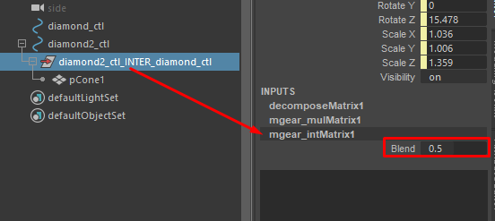
Usage:
Select the first object (A)
Select the second object (B)
Run Interpolate Transform
Creates a new transform with _INTER_ naming that interpolates 50% between both objects. Uses gear_intmatrix_op for smooth matrix-based blending.
Connect Local SRT
Connect Scale, Rotation, and/or Translation attributes between objects.
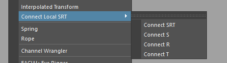
Options:
Connect SRT - Connect all three (Scale, Rotation, Translation)
Connect S - Scale only
Connect R - Rotation only
Connect T - Translation only
Usage:
Select the source object (first)
Select target objects
Choose which attributes to connect
Channel Wrangler
Move or proxy channels between nodes with a visual table interface.
With mGear file drop enabled (see File Drop), dropping a .cwc file into Maya applies its channel rules.
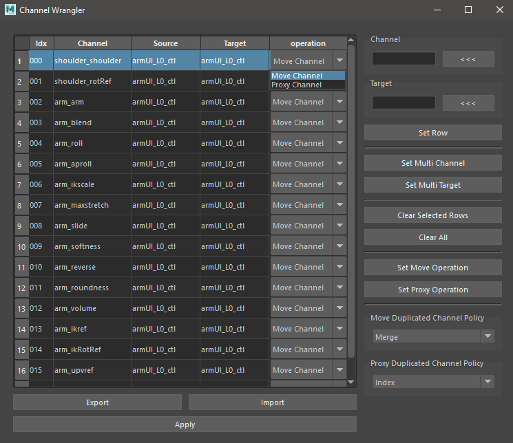
Operation Modes:
Move Channel - Physically move the channel from source to target
Proxy Channel - Create a proxy attribute that mirrors the source
Move Policies:
merge - Merge with existing channels
index - Match by channel index
fullName - Match by full attribute name
Proxy Policies:
index - Match by channel index
fullName - Match by full attribute name
UI Features:
Visual table with Index, Channel, Source, Target, Operation columns
Channel and Target line edits with picker buttons
Set Multi-Channel and Set Multi-Target for batch operations
Import/Export configurations as .cwc JSON files
Eye Rigger
Automatic eyelid rigging tools.
Eye Rigger 3.0

Open it from mGear > Rigbits > Facial Rigger 3.0 (Eye tab). It builds the same eyelid rig as Eye Rigger 2.1, with these changes:
Vertex or edge loop: rig from a selected vertex loop (the default) or set Loop Type to Edge. Eye Rigger 2.1 configurations build from their edge loop.
Any eye orientation: corners and the upper and lower lids are found in the loop’s own frame, so tilted and side facing eyes work without the scene up axis. Side Range remains as an override.
Mirror Behavior (on by default): the right side controls mirror the left ones, so the same values give a mirrored pose. The aim control doesn’t mirror: the same rotation aims both eyes the same way. Joint names are the same as 2.1, numbered from the inner corner on both sides, so existing skin files still load.
Shared settings: the settings are also used by the upcoming Shifter eyelid component. Export Config saves a
.eyesfile and Import Config loads 3.0 and 2.1 files.Simplified controls are on by default: the blink controls also move the mid eyelid point. Eye Rigger 2.1 configurations keep their setting.
Smooth contact: near the end of a blink the lids blend to the closed shape, so they meet without a jump.
Fixes: a joint every 0 vertex, the fixed joint count on the lower lid, name clashes when building both eyes, the lower lid moving off the mesh at rest, and the lids opening at full blink.
Every option has a tooltip, and the controls and deformers sets can be picked from the selection.
Scripts and custom steps build from a file with
mgear.rigbits.facial_rigger3.eye.rig_from_file(path), or the Import
Facial Rigger 3.0 Configuration custom step template. Existing scripts and
custom steps using mgear.rigbits.facial_rigger2.eye_rigger keep building
the Eye Rigger 2.1 rig.
Eye Rigger 2.1
The previous eye rigger, in mGear > Rigbits > Facial Legacy > Eye Rigger 2.1. Its configuration files load in Eye Rigger 3.0.
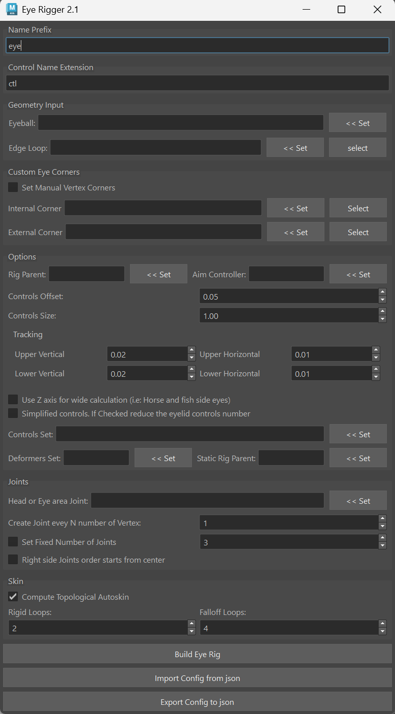
Key Features:
Automatic upper/lower eyelid rigging from edge loops
Multiple joint distribution options (every N vertex, fixed count, from center)
Simplified mode for lighter rigs
Customizable control size
Auto-skin with topological propagation
Vertical/Horizontal tracking attributes
Blink height offset parameter
Workflow:
Select the eye mesh
Pick the eyelid edge loop
Set corner vertices (automatic or manual)
Configure joint distribution settings
Set naming prefix
Build the rig
Parameters:
Edge Loop - The eyelid edge loop to rig
Corner Vertices - Inner and outer corner vertex selection
Prefix - Naming prefix for created nodes
Offset - Surface offset distance (default 0.05)
Rigid/Falloff Loops - Control density settings
Head Joint - Reference joint for parenting
Do Skin - Enable automatic skinning
Simplified - Create simplified rig version
Eye Rigger (Legacy)
The original eye rigger for backward compatibility.
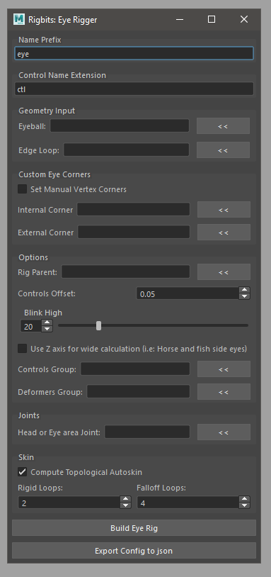
Similar functionality to version 2.1 with the original parameter set including blink height percentage control.
Lips Rigger
Automatic lip rigging from the loop between the lips.
Lips Rigger 3.0

Open it from mGear > Rigbits > Facial Rigger 3.0 (Lips tab). It builds a lips rig with 7 upper and 5 lower controls (corners and centers, plus two in-between controls per side), one joint per loop vertex and an optional topological autoskin.
Vertex or edge loop: rig from the closed vertex loop where the lips meet (the default), or set Loop Type to Edge.
No mid vertex picking: the corners and the upper and lower lips are found from the loop, in a mouth frame facing the scene front. For a rotated head, set Mouth Front to a transform in front of the mouth. Check Detection selects the upper lip found; if it is the lower one, turn on Invert Upper/Lower.
Jaw follow: each corner control has a
jawFollowattribute, from 0 (follows the upper reference) to 1 (follows the lower reference). The upper lip follows the Upper Reference (or the head joint), the lower lip the Lower Reference (or the jaw joint).Zipper:
zipperon each corner zips the lips from that corner to the center.zipperHeighton the upper control sets where they meet (0 lower lip, 1 upper lip). Zipper Falloff sets how soft the zip is. The lips meet at their surface, without crossing, and keep their orientation while zipping.Squash and stretch (optional): the lips get thinner when stretched and thicker when compressed.
squashStretchon the upper and lower controls turns it down or off for each lip.Lip roll:
rollon the upper and lower controls curls that lip out (positive) or in, fading to the corners when Roll Falloff is on.Joints: one joint every N vertices, or a fixed number per lip. Rope Points sets the points of the curves the joints slide on: fewer points give smoother lip shapes, more points follow the controls closer.
Mirror Behavior (on by default): the right side controls mirror the left ones, and the mGear mirror and flip pose tools pair them.
secondaryVison the upper control hides the in-between controls.Autoskin: the lip joints are skinned to the vertex rings around the loop. Smooth Iterations blends the weights between neighbor joints and around the mouth corners, to avoid pinching.
Shared settings: Export Config saves a
.lipsfile, shared with thelips_01Shifter component. Import Config loads 3.0 and 1.0 files. 1.0 mid vertex picks are not used anymore.
Scripts and custom steps build from a file with
mgear.rigbits.facial_rigger3.lips.rig_from_file(path), or the Import
Facial Rigger 3.0 Configuration custom step template.
Lips Rigger 1.0
The previous lips rigger, in mGear > Rigbits > Facial Legacy > Facial Rigger 1.0. Its configuration files load in Lips Rigger 3.0.
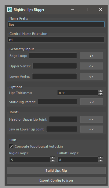
Key Features:
Lip edge loop setup for upper and lower lips
Central vertex selection for proper topology handling
Thickness parameter for offset control
Rigidity and falloff density settings
Head and jaw joint references
Automatic shape and control creation
Workflow:
Select the lip edge loop
Set the upper central vertex
Set the lower central vertex
Configure thickness and density settings
Set head and jaw joint references
Build the rig
Parameters:
Edge Loop - The lip edge loop
Up Vertex - Upper central vertex
Low Vertex - Lower central vertex
Thickness - Offset amount (default 0.3)
Rigid Loops - Rigidity density (default 5)
Falloff Loops - Falloff density (default 8)
Head Joint - Head reference joint
Jaw Joint - Jaw reference joint
Brow Rigger
Brow Rigger 3.0

Open it from mGear > Rigbits > Facial Rigger 3.0 (Brow tab). It builds one brow per run: a left, right or center brow. Build the left and right brows, then the center one if needed.
Vertex or edge path: an open path along the brow, ordered from the inner to the outer end (the center brow runs right to left). The side is found from the path, or set with Side. For a rotated head, set Brow Front to a transform in front of the brow.
Controls: a whole brow control, Main Controls along the brow with tangent controls at both ends, and an optional row of Secondary Controls riding the main ones.
Squeeze:
squeezeon the whole brow control slides the inner brow toward the center (Squeeze Distance), fading to the outer end.Center brow: with side C, Hook Left and Hook Right make its ends follow the inner controls of the side brows (
brow_L_in_ctl,brow_R_in_ctl).Slide surface (optional): set a NURBS surface with the skull shape and the control points slide on it, keeping their distance, so the brow follows the skull. Each control gets a
surfaceOffsetchannel to move it off the surface.Joints Rotate with Curve (on by default): the joints aim along the brow curve. Turn it off for joints that only translate, keeping the brow orientation.
Shared options: joint count, mirrored right side controls,
secondaryVis, and the smoothed topological autoskin.Config files: Export Config saves a
.browsfile, shared with thebrow_01Shifter component. Import Config loads 3.0 and 1.0 files. 1.0 symmetry files build one brow; build the others separately.
Scripts and custom steps build from a file with
mgear.rigbits.facial_rigger3.brow.rig_from_file(path), or the Import
Facial Rigger 3.0 Configuration custom step template. The previous Brow
Rigger stays in Facial Legacy > Facial Rigger 1.0.
Proxy Geo
Create proxy geometry for joints with multiple creation modes.
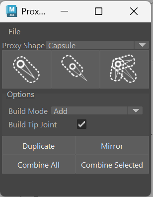
Creation Modes:
Proxy to Next - Extends geometry toward the next joint in chain
Proxy Centered - Creates geometry centered at joint position
Proxy to Children - Aims geometry at child joints
Shape Types:
Capsule - Rounded cylinder shape
Box - Rectangular box shape
Build Modes:
Add - Add new proxy geometry
Replace - Replace existing proxy geometry
Features:
Duplicate and Mirror existing proxies
Combine multiple proxies into single mesh
Export/Import proxy configurations as .pxy files
Automatic axis alignment
Build Tip Joint option for end joints
Proxy Attributes:
Created proxies have custom attributes for identification and configuration:
isProxy- Boolean markerproxy_shape- “capsule” or “box”proxy_axis- Axis alignmentside/length- Dimension attributes
Proxy Slicer
Create proxy geometry by analyzing skin cluster weights and splitting the mesh per joint influence. Uses OpenMaya2 for fast batch weight queries.
How it works:
Batch-queries all skinCluster weights via OpenMaya2 (single API call)
Groups faces by their dominant joint influence
Creates separate proxy meshes per joint
Names proxies as
JointName_ProxyHandles locked transforms from skinned meshes (unlocks for operations, re-locks after parenting)
Usage:
Select one or more skinned meshes and run Proxy Slicer. The system automatically creates proxy geometry based on skin weights, with each proxy representing the area most influenced by that joint. Multiple meshes are processed in sequence.
Works with meshes that have additional deformers after the skinCluster (softMod, cluster, etc.) since it searches the full deformation history.
Proxy Slicer Parenting
Same as Proxy Slicer but parents the created proxies directly under their influence joints instead of grouping them separately.
Difference from Proxy Slicer:
Proxy Slicer - Creates a ProxyGeo group with matrix constraints to influence joints
Proxy Slicer Parenting - Parents proxies directly under influence joints, re-locks transform attributes
Python API:
from mgear.rigbits import proxySlicer

# Slice a single mesh (world-space mode with matrix constraints)
proxySlicer.slice(parent=False, oSel="body_geo")

# Slice with direct parenting under influence joints
proxySlicer.slice(parent=True, oSel="body_geo")

# Slice multiple meshes
proxySlicer.slice(oSel=["body_geo", "head_geo", "hands_geo"])

# Slice current selection (supports multi-select)
proxySlicer.slice()

# Slice current selection with parenting
proxySlicer.slice(parent=True)
SDK Manager
The SDK Manager is a tool for creating and managing Set Driven Keys (SDKs) in mGear rigs. It provides a streamlined workflow for setting up SDK-based facial rigs and corrective shapes using joints.
Overview
The SDK Manager workflow is based on Judd Simantov’s facial rigging techniques, using joints and SDKs to create facial shapes with the control of joints and weighting rather than blendshapes.
Advantages:
Same results as blendshape-based face rigs with extreme control over every shape
Expose tweak controls for every joint to animators
Fits into the rebuild workflow - pivots and controllers can be altered without destroying rig work
Export/import weight maps, guides, and SDKs between characters
Can add blendshapes on top for further deformation
SDK Tab
The main SDK tab provides the core functionality for setting driven keys.
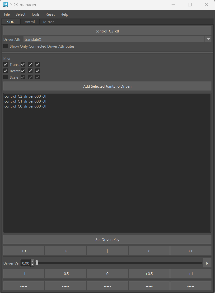
Driver Section:
Click the Driver button with a control selected to set it as the driver
Choose the Driver Attribute from the dropdown to select which attribute drives the SDKs
Enable Show Only Connected Driver Attributes to filter the dropdown to attributes that already have SDKs
Key Channels:
Select which channels to key on the driven controls:
Translate - with individual X, Y, Z checkboxes
Rotate - with individual X, Y, Z checkboxes
Scale - with individual X, Y, Z checkboxes
This allows you to key only specific axes (e.g., only Translate Y and Rotate Z) rather than all channels.
Driven Section:
Click Add Selected Joints To Driven to add SDK controls to the driven list
Select items in the list and click Set Driven Key to create SDKs at current values
Use the navigation buttons (<<, <, |, >, >>) to jump between existing key values
Use the Driver Val slider and spin box to scrub the driver value
The -1, -0.5, 0, +0.5, +1 buttons provide quick value adjustments
Save Slots:
The five save slot buttons allow you to store and recall SDK control positions:
Click with controls selected to save their current values
Click again to restore saved values
Ctrl+Click to clear the slot
Right-Click Menu
Right-click on items in the driven list for additional options:
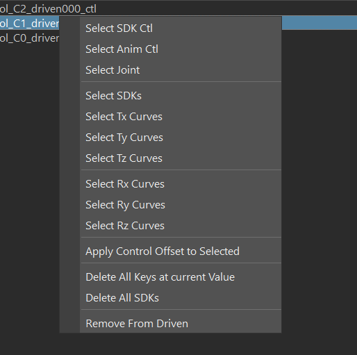
Select SDK Ctl - Select the SDK control in the viewport
Select Anim Ctl - Select the animation tweak control
Select Joint - Select the driven joint
Select SDKs - Select all SDK animation curves
Select Tx/Ty/Tz/Rx/Ry/Rz Curves - Select specific channel curves
Apply Control Offset to Selected - Match driven controls to driver position
Delete All Keys at current Value - Remove keys at the current driver value
Delete All SDKs - Remove all SDKs from selected items
Remove From Driven - Remove items from the driven list
Controls Tab
The Controls tab provides tools for setting transform limits on SDK controls.
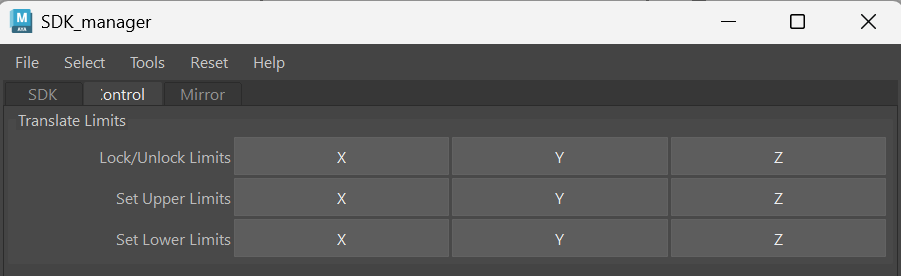
Lock/Unlock Limits - Toggle transform limits on X, Y, Z axes
Set Upper Limits - Set upper limit from current position
Set Lower Limits - Set lower limit from current position
Mirror Tab
The Mirror tab allows mirroring SDKs between left and right controls.

Select driver controls and click Mirror SDK’s From Selected Ctls X+ To X- to copy SDKs to the opposite side
Wire to Skinning
A tool for creating wire deformers and converting them to skin clusters using the de Boor algorithm for NURBS-based weight computation.
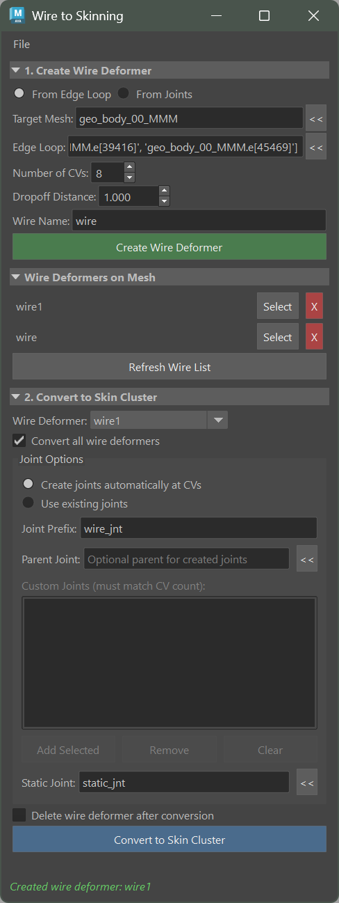
Overview
Wire to Skinning provides a workflow for:
Creating wire deformers from edge loops or joints
Converting wire deformers to skin clusters with precise B-spline weight distribution
Export/Import configurations for reusable wire setups
This tool is particularly useful for facial rigging, secondary deformation, and any setup requiring smooth, NURBS-based weight falloff.
Tip
Wire deformers are excellent for quick deformation tests. Use this tool to convert your wire setup to production-ready skin clusters once you’re happy with the result.
Create Wire Section
The top section allows creating wire deformers using two methods:
Edge Loop Mode:
Select edges from the mesh to define the wire curve path
Specify the number of CVs for the curve (more CVs = more joints/control)
The curve is rebuilt to match the target CV count
Joint Mode:
Select existing joints to define the wire curve
The curve CVs are connected to joints via
mgear_curveCnsdeformerMoving joints automatically updates the wire curve
Joint ordering options: Selection order, Hierarchy, or Position X
Common Parameters:
Mesh - Target mesh for the wire deformer
Wire Name - Base name for the created wire deformer
Dropoff - Wire influence falloff distance
Existing Wires Section
Displays all wire deformers currently affecting the selected mesh.
Refresh - Update the wire list
Select - Select the wire deformer in Maya
Remove - Delete the wire deformer and its curves
Convert to Skin Section
Converts wire deformers to skin clusters using the de Boor algorithm for B-spline basis function evaluation.
Wire Selection:
All Wires - Convert all wire deformers on the mesh
Selected Wire - Convert only the selected wire from the dropdown
Joint Options:
Auto-create joints - Create joints at each curve CV position
Prefix - Naming prefix for auto-created joints
Parent Joint - Optional parent for the joint chain
Custom joints - Use manually specified joints (must match CV count)
Conversion Parameters:
Static Joint - Joint for vertices outside wire influence (default:
static_jnt)Delete Wire - Remove the wire deformer after conversion
How Conversion Works:
For each vertex, finds the closest point on the wire curve
Computes B-spline basis functions at that parameter using de Boor’s algorithm
Distributes weights across nearby joints based on curve continuity
Blends with existing skin weights or assigns to static joint for unaffected areas
Tip
When converting a wire created from joints, the tool automatically uses those connected joints for skinning - no need to manually specify them.
Configuration Export/Import
Save and load wire configurations for reuse across scenes or characters.
File Menu:
Export Configuration - Save wire setup to a
.wtsfileImport Configuration - Load wire setup from a
.wtsfile
Exported Data:
Wire deformer settings (dropoff, scale, envelope)
Curve CV positions
Connected joint names (for joint-mode wires)
Conversion settings
Import Behavior:
Recreates wire deformers from saved curve data
For joint-connected wires, automatically reconnects to existing joints
Falls back to static curves if referenced joints don’t exist
Tip
Enable mGear file drop (see File Drop) to import .wts files by dragging them into Maya’s viewport.
Scripting Access
The tool’s core functions are available for scripting:
from mgear.rigbits import wire_to_skinning

# Show the UI
wire_to_skinning.show()

# Create wire from edges
positions = wire_to_skinning.get_edges_positions(edges)
curve = wire_to_skinning.create_curve_from_positions(positions, num_cvs=8)
wire = wire_to_skinning.create_wire_deformer(mesh, curve, dropoff_distance=5.0)

# Create wire from joints
wire, curve, curvecns = wire_to_skinning.create_wire_from_joints(
    mesh, joints, dropoff_distance=5.0, name="lip_wire"
)

# Convert wire to skin
curve_info = wire_to_skinning.get_curve_info(curve)
wire_info = wire_to_skinning.get_wire_deformer_info(wire)
weights, uses_static = wire_to_skinning.compute_skin_weights_deboor(
    mesh, curve_info, wire_info, wire_deformer=wire
)
joints = wire_to_skinning.create_joints_at_cvs(curve_info, prefix="lip")
skin = wire_to_skinning.create_skin_cluster(mesh, joints, weights)

# Export/Import configuration
wire_to_skinning.export_configuration(mesh, "/path/to/config.wts")
wire_to_skinning.import_configuration("/path/to/config.wts", target_mesh=mesh)
Core Module Functions:
The underlying functions are also available in mgear.core modules:
mgear.core.curve.getCurveInfo()- Get curve CVs, degree, knotsmgear.core.deformer.createWireDeformer()- Create wire deformermgear.core.deformer.getWireDeformerInfo()- Get wire deformer attributesmgear.core.deformer.getWireWeightMap()- Get per-vertex wire weightsmgear.core.deformer.getMeshWireDeformers()- Find wire deformers on meshmgear.core.skin.getCompleteWeights()- Get skin weights by vertex
Evaluation Partition
The Evaluation Partition tool splits a mesh into polygon group partitions to optimize Maya’s parallel evaluation. By dividing a dense mesh into independent sub-meshes, each partition can be evaluated in parallel, improving playback performance for complex character rigs.
Access from the menu: mGear > Rigbits > Evaluation Partition
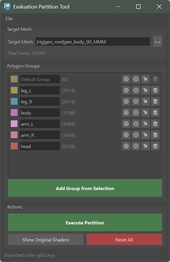
Overview
The tool works by defining polygon groups on a source mesh and then executing an 8-step pipeline that creates independent partition meshes with all deformers transferred.
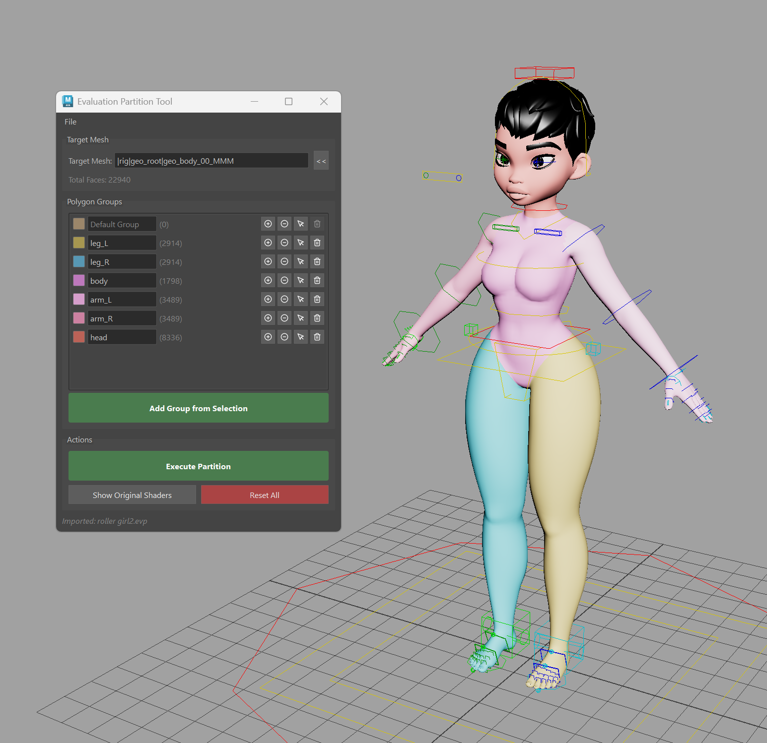
Polygon Groups
Define which faces belong to each partition using the Polygon Groups section.
Default Group: Contains all faces not assigned to other groups
Add Group from Selection: Select faces in the viewport and click to create a new group
Add/Remove faces: Use the
+and-buttons on each group to add or remove selected facesSelect: Click to select the group’s faces in the viewport
Color coding: Each group displays with a unique color shader for visual reference
Pipeline Steps
When you click Execute Partition, the tool runs an 8-step pipeline:
Split Polygon Groups: Creates independent meshes from each polygon group
Transfer Blendshapes: Captures blendshape targets via wrap-based baking, including in-between targets
Clean Unused BS Targets: Removes targets with zero delta on each partition
Reconnect BS Inputs: Replicates weight driver connections. For combo targets (multiply networks from SHAPES or similar), builds independent multiply chains per partition
Copy Skin Clusters: Transfers skin weights from source to each partition
Remove Unused Influences: Cleans influences with zero weight on each partition
Copy Skin Configuration: Copies skinCluster settings (skinningMethod, normalizeWeights, dqsScale connections, prebind matrices). Reproduces localized skinCluster connections (
mgear_mulMatrix) if the source useslocalize_skin_clustersProximity Wrap Proxy: Creates a proxy mesh with proximity wrap for any remaining deformation
Visibility Controls
Per-partition visibility attributes are created on the partitions root group node, allowing individual partitions and the proxy geometry to be toggled on and off.
Configuration
Save and load partition configurations using the File menu.
Export Configuration: Save polygon groups and settings to a
.evpfileImport Configuration: Load a previously saved
.evpfile
Scripting Access
Launch the UI:
from mgear.rigbits import evaluation_partition
evaluation_partition.show()
Run from a .evp configuration file
execute_from_file is the main entry point for pipeline automation and scripting. It loads a .evp file, creates a PolygonGroupManager, and assigns the partition shaders to the mesh. It does not run the 8-step pipeline by itself — it only prepares the manager so you can inspect it, modify it, or feed it to the pipeline.
from mgear.rigbits import evaluation_partition as evp

# Load the config and build the manager (shaders are created and assigned)
manager = evp.core.execute_from_file("D:/configs/character_body.evp")

# Optional: override the mesh stored in the config
# manager = evp.core.execute_from_file(
#     "D:/configs/character_body.evp",
#     mesh="body_geo",
# )
Returns: a PolygonGroupManager instance, or None if loading failed.
The manager holds the in-memory state reconstructed from the .evp file:
manager.mesh— target mesh (long name)manager.groups— list ofPolygonGroupobjects, each withname,color,face_indices,shader_node, andshading_group
This is useful for:
Feeding the pipeline. Every step function takes a manager as input.
execute_from_fileis the scripted way to get one without opening the UI.Previewing / QC. Shaders are already assigned, so you can visually verify the partition in the viewport before executing the split.
Inspecting or tweaking groups in code. Iterate
manager.groupsto validate face counts, rename, recolor, or adjust face assignments (add_faces_to_group,remove_faces_from_group,update_group_color,rename_group) before running the pipeline.Running a subset of steps on the same manager (e.g. only split + skin copy, skipping blendshapes).
Run the full 8-step pipeline
The typical scripted flow is: load the config, then hand the manager to execute_full_pipeline.
from mgear.rigbits import evaluation_partition as evp

manager = evp.core.execute_from_file("D:/configs/character_body.evp")

# Optional: inspect or modify the manager here
# for group in manager.groups:
#     print(group.name, len(group.face_indices))

grp, partitions, proxy = evp.core.execute_full_pipeline(manager)
Run individual pipeline steps
If you only need a subset of the pipeline, call the step functions directly on the manager. Step 1 (split_polygon_groups) must run first because it produces the partition meshes that every later step operates on.
from mgear.rigbits import evaluation_partition as evp

manager = evp.core.execute_from_file("D:/configs/character_body.evp")

# Step 1 — split the source mesh into partition meshes
grp, partitions = evp.core.split_polygon_groups(manager)

source = manager.mesh

# Step 2 — transfer blendshapes
evp.core.transfer_blendshapes(source, partitions)

# Step 3 — clean unused BS targets
evp.core.clean_unused_bs_targets(partitions)

# Step 4 — reconnect BS input connections
evp.core.reconnect_bs_inputs(source, partitions)

# Step 5 — copy skin clusters
evp.core.copy_skin_clusters(source, partitions)

# Step 6 — remove unused influences
evp.core.remove_unused_influences(partitions)

# Step 7 — copy skin configuration and reproduce localization
evp.core.copy_skin_configuration(source, partitions)
evp.core.reproduce_skin_localization(source, partitions)

# Step 8 — create the proximity wrap proxy
proxy = evp.core.create_proximity_wrap_proxy(source, partitions, grp, manager)
.evp configuration format
As of schema v2.0, .evp files store the target mesh as a short name rather than a full DAG path. This makes configurations portable across scenes, namespaces, and rig reorganizations — the tool resolves the short name to the actual node in the current scene at load time.
Backwards compatibility:
Existing v1.0
.evpfiles (which store the long path) still load. If the stored long path still resolves, it is used verbatim; otherwise the tool falls back to a short-name lookup using themesh_short_namefield.Re-saving a v1.0 file writes it out as v2.0 automatically.
Ambiguity:
If the short name in a config matches more than one mesh transform in the current scene,
apply_configurationraisesRuntimeErrorlisting every match. Rename the conflicting nodes, or passmesh=explicitly to disambiguate:manager = evp.core.execute_from_file( "D:/configs/character_body.evp", mesh="|rig|geo|body", # explicit long path wins )
Blendshape Setup Transfer
The Blendshape Setup Transfer tool transfers blendshape targets from one or more source meshes into a single blendShape node on a target mesh. It supports combo multiply networks, in-between targets, and preserves all alias names.
Access from the menu: mGear > Rigbits > Blendshape Setup Transfer
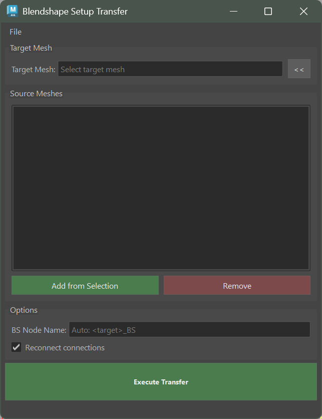
Features
Multi-Source Transfer
Transfer blendshape targets from multiple source meshes simultaneously. All targets are stacked into a single blendShape node on the target mesh with unique alias names. Name collisions are resolved by prefixing the source mesh name.
Combo Network Rebuild
For targets driven by SHAPES combo connections (multiply networks using multDL or multDoubleLinear nodes), the tool rebuilds an independent multiply chain on the target blendShape. The source combo network is never modified.
Zero-Delta Cleanup
Targets that produce no visible deformation on the target mesh are automatically detected and skipped during transfer, keeping the result clean.
Connection Reconnection
Simple weight drivers (animCurves, weightDrivers, etc.) are connected from the source to the corresponding target weight. Combo networks are rebuilt from scratch using the target’s own weights as inputs.
Usage
Set the Target Mesh using the
<<button to load from selectionAdd one or more Source Meshes using Add from Selection
Optionally set a custom BS Node Name
Enable or disable Reconnect connections
Click Execute Transfer
Configuration
Save and load transfer configurations using the File menu.
Export Config: Save target, sources, and options to a
.bstfileImport Config: Load a previously saved
.bstfile and populate the UI
Scripting Access
from mgear.core import blendshape

# Transfer from multiple sources to a target
result = blendshape.transfer_blendshapes(
    sources=["source_head", "source_jaw"],
    target="target_body",
    bs_node_name="body_BS",
    reconnect=True,
)

# Run from a saved config file
from mgear.rigbits.blendshape_transfer import core
config = core.import_config("/path/to/config.bst")
core.run_from_config(config)
Lattice IO
Lattice IO exports ffd lattice deformers to a .lat file and rebuilds them, so hand-placed lattices survive a rig rebuild. Use the tool to export, then rebuild the lattices in the Shifter build with the Import Lattice Configuration custom step template.
Access from the menu: mGear > Rigbits > Lattice IO
With mGear file drop enabled (see File Drop), dropping a .lat file into Maya rebuilds its lattices.
What is Saved
ffd settings: local influence, outside lattice and falloff, partial resolution, bind to original geometry, freeze geometry and envelope
Lattice and base: names, parent, world matrix and visibility
Lattice shape: divisions and the position of every lattice point
Affected geometry: the deformed shapes, their deformer set members or component tag expression, and the weight map (only the weights that are not 1.0 are stored)
Deformer order: the deformer stack of each geometry and the order mode chosen on export
Export

Open the Export tab. It lists the lattices in the scene. Use From Selection to select the lattices of the selected objects (lattices, base lattices or deformed geometry).
Choose the Deformer order to store with the lattices (see below). It always starts as Current when the tool opens.
Click Export Selected… and save the
.latfile.
Import

Open the Import tab and browse to a
.latfile, or use File > Recent Files. The file content is listed with the divisions, the geometry and whether weights are stored.Uncheck the lattices you don’t want to import.
The Order column shows the deformer order stored for each lattice. Change it to override it for this import only.
Keep Replace existing checked to delete lattices with the same names first, including an orphan lattice or base node left by a broken setup in the place the lattice is rebuilt, so the rebuilt nodes keep their exact names. Nodes with the same names elsewhere in the scene are not touched.
Click Import Checked. The whole import is a single undo step.
Geometry and parents are found by name, even if they moved in the hierarchy or are in another namespace. Missing geometry is skipped with a warning in the log panel.
Note
Component tag expressions are restored, but the component tags themselves are not saved. Make sure the tags exist on the rebuilt geometry.
Deformer Order
The deformer order sets where the ffd goes in the deformer stack of each geometry:
Current (as exported): the position the ffd had when it was exported. It goes directly after the closest deformer that was evaluated before it and still exists. If the ffd was the first deformer, it goes to the front of the chain. If its position can’t be found, it is added last.
Front of chain: before all the existing deformers.
Last (append): after all the existing deformers, the same as applying a new lattice.
The order chosen on export is saved for each lattice in the .lat file, so the custom step and scripted imports rebuild the lattices in the intended order without extra settings.
Shifter Custom Step
Create a custom step from the Import Lattice Configuration template (see Custom Step Templates) and set its options in setup():
self.lattice_path: the.latfile. Leave it asNoneto pick the file when the step runs.self.lattice_names: the ffd names to import,Nonefor all.self.replace: delete lattices with the same names first.self.order:Noneuses the order stored in the file. Use"current","front"or"last"to override it.
File Format
.lat files are JSON. The type key is "lattice_config". Files exported as .json with the same content (from the original lattice serializer script) can also be imported.
Scripting Access
from mgear.rigbits import lattice_io

# Export
lattice_io.export_lattices(["face_ffd", "belly_ffd"], "C:/rig/data/lattices.lat")

# Import everything with the stored order
lattice_io.import_lattices("C:/rig/data/lattices.lat")

# Import one lattice, appended after the existing deformers
lattice_io.import_lattices(
    "C:/rig/data/lattices.lat",
    names=["face_ffd"],
    order="last",
)

# Override the order per lattice
lattice_io.import_lattices(
    "C:/rig/data/lattices.lat",
    order={"face_ffd": "front"},
)
The generic helpers used by the tool are available in mgear.core.deformer for other tools: get_deformer_stack, move_deformer, get_deformer_weights, set_deformer_weights, get_lattice_points, set_lattice_points, find_ffd_nodes and delete_lattice.
Shrink Wrap IO
Shrink Wrap IO exports Maya shrinkWrap deformers to a .shw file and rebuilds them, so the shrink wraps used to fit clothing, accessories or proxies onto a body survive a rig rebuild. It works the same way as Lattice IO: export with the tool, then rebuild the shrink wraps in the Shifter build with the Import Shrink Wrap Configuration custom step template.
Access from the menu: mGear > Rigbits > Shrink Wrap IO
With mGear file drop enabled (see File Drop), dropping a .shw file into Maya rebuilds its shrink wraps.
What is Saved
Settings: projection, closest if no intersection, reverse, bidirectional, axis options, offset, target inflation, falloff and falloff iterations, shape preservation, target smoothing (smooth level, continuity, UVs, borders, hard edges) and envelope
Target mesh: the mesh the geometry is wrapped onto
Connections: every connection driving the shrink wrap, apart from the deformed geometry itself: the target and optional inner mesh, and any rig control driving a setting such as the envelope
Affected geometry: the deformed shapes, their deformer set members or component tag expression, and the weight map (only the weights that are not 1.0 are stored)
Deformer order: the deformer stack of each geometry and the order mode chosen on export
Export

Open the Export tab. It lists the shrink wraps in the scene with their target. Use From Selection to select the shrink wraps of the selected objects: shrink wraps, deformed geometry, or target and inner meshes.
Choose the Deformer order to store with the shrink wraps (see Lattice IO for the modes). It always starts as Current when the tool opens.
Click Export Selected… and save the
.shwfile. Shrink wraps without a target mesh are skipped with a warning.
Import

Open the Import tab and browse to a
.shwfile, or use File > Recent Files. The file content is listed with the target, the geometry and whether weights are stored.Uncheck the shrink wraps you don’t want to import.
Change the Order of a shrink wrap to override the stored deformer order for this import only.
Keep Replace existing checked to delete shrink wraps with the same names first. Only the shrink wrap node is deleted: the target and deformed meshes are kept.
Click Import Checked. The whole import is a single undo step.
The target mesh must exist in the scene: a shrink wrap whose target can’t be found is skipped with a warning. Geometry, targets and driving controls are found by name, even if they moved in the hierarchy or are in another namespace. A missing driving control is reported in the log panel and the setting keeps the exported value.
Shifter Custom Step
Create a custom step from the Import Shrink Wrap Configuration template (see Custom Step Templates) and set its options in setup():
self.shrinkwrap_path: the.shwfile. Leave it asNoneto pick the file when the step runs.self.shrinkwrap_names: the shrink wrap names to import,Nonefor all.self.replace: delete shrink wraps with the same names first.self.order:Noneuses the order stored in the file. Use"current","front"or"last"to override it.
Run the step after the target meshes and the controls that drive the shrink wraps exist in the rig.
File Format
.shw files are JSON. The type key is "shrinkwrap_config".
Scripting Access
from mgear.rigbits import shrinkwrap_io

# Export
shrinkwrap_io.export_shrinkwraps(["shirt_sw", "belt_sw"], "C:/rig/data/cloth.shw")

# Import everything with the stored order
shrinkwrap_io.import_shrinkwraps("C:/rig/data/cloth.shw")

# Import one shrink wrap, appended after the existing deformers
shrinkwrap_io.import_shrinkwraps(
    "C:/rig/data/cloth.shw",
    names=["shirt_sw"],
    order="last",
)
Lattice IO and Shrink Wrap IO share mgear.core.deformer_io, a generic layer to save and rebuild deformers (file envelope, deformer order modes, geometry data, attributes and connections). Use it to add the same workflow to other deformer types.
Proximity Wrap IO
Proximity Wrap IO exports Maya proximityWrap deformers to a .pxw file and rebuilds them, so the proximity wraps used for clothing, accessories, proxies or partitioned meshes survive a rig rebuild. It works the same way as Lattice IO and Shrink Wrap IO: export with the tool, then rebuild the proximity wraps in the Shifter build with the Import Proximity Wrap Configuration custom step template.
Access from the menu: mGear > Rigbits > Proximity Wrap IO
With mGear file drop enabled (see File Drop), dropping a .pxw file into Maya rebuilds its proximity wraps, with a warning when the skinned meshes are not at their bind pose.
What is Saved
Settings: wrap mode, falloff and dropoff rate scale, scale compensation, coordinate frames, smooth normals, span samples, smooth influences, soft normalization, bind tags, max drivers and envelope, plus the falloff ramp
Drivers: every driver mesh, in order, with its own settings (falloff start and end, dropoff rate, strength, use transform as deformation, scale compensation, smooth normals, span samples and smooth influences with their overrides, driver wrap mode) and its own falloff ramp
Connections: every connection driving the proximity wrap, apart from the deformed geometry and the driver meshes themselves, for example a rig control driving the envelope or a driver strength
Affected geometry: the deformed shapes, their deformer set members or component tag expression, and the weight map (only the weights that are not 1.0 are stored)
Deformer order: the deformer stack of each geometry and the order mode chosen on export
Export

Open the Export tab. It lists the proximity wraps in the scene with their number of drivers and geometry. Use From Selection to select the proximity wraps of the selected objects: proximity wraps, deformed geometry, driver meshes or controls driving them. Selecting a proximity wrap in the list selects its driver meshes.
Choose the Deformer order to store with the proximity wraps (see Lattice IO for the modes). It always starts as Current when the tool opens.
Click Export Selected… and save the
.pxwfile. Proximity wraps without drivers are skipped with a warning.
Import

Open the Import tab and browse to a
.pxwfile, or use File > Recent Files. The file content is listed with the drivers, the geometry and whether weights are stored.Uncheck the proximity wraps you don’t want to import.
Change the Order of a proximity wrap to override the stored deformer order for this import only.
Keep Replace existing checked to delete proximity wraps with the same names first. Only the proximity wrap node is deleted: the driver and deformed meshes are kept.
Click Import Checked. The whole import is a single undo step.
Important
Like when a driver is added in Maya, the drivers are bound again at their shape when you import. Import with the rig at bind pose. In a Shifter build, custom steps run at bind pose.
Missing driver meshes are skipped with a warning, and the proximity wrap is built with the drivers that exist. A proximity wrap with no driver left is skipped. Geometry, drivers and driving controls are found by name, even if they moved in the hierarchy or are in another namespace. Settings that don’t exist in your Maya version are skipped and listed in the log panel.
Shifter Custom Step
Create a custom step from the Import Proximity Wrap Configuration template (see Custom Step Templates) and set its options in setup():
self.proximitywrap_path: the.pxwfile. Leave it asNoneto pick the file when the step runs.self.proximitywrap_names: the proximity wrap names to import,Nonefor all.self.replace: delete proximity wraps with the same names first.self.order:Noneuses the order stored in the file. Use"current","front"or"last"to override it.
Run the step after the driver meshes and the controls that drive the proximity wraps exist in the rig.
File Format
.pxw files are JSON. The type key is "proximitywrap_config".
Scripting Access
from mgear.rigbits import proximitywrap_io

# Export
proximitywrap_io.export_proximitywraps(["shirt_pw"], "C:/rig/data/cloth.pxw")

# Import everything with the stored order
proximitywrap_io.import_proximitywraps("C:/rig/data/cloth.pxw")
To create a proximity wrap from a script, use mgear.core.deformer.create_proximity_wrap. Its optional wrap_mode argument sets the wrap mode, as an index or a name ("offset", "surface", "snap", "rigid" or "cluster"). When it is not given, Maya’s default (surface) is kept.
from mgear.core import deformer

deformer.create_proximity_wrap("shirt", ["body", "arms"], wrap_mode="snap")
SDK Creator
Reads keyframed poses from the timeline and creates Set Driven Key setups. It converts animation data into SDK transform nodes with animCurve graphs driven by attributes on a UIHost control.
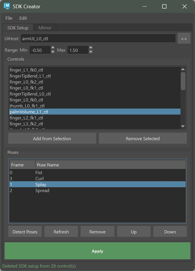
Workflow
Select a UIHost control (the node that will hold the driver attributes)
Add the controls that have keyframed poses on the timeline
Click Detect Poses to read keyframes — the tool finds all keyed frames and lists them with editable pose names
Adjust the Min/Max range for the driver attributes (default 0–1)
Click Apply to generate the SDK setup
The tool creates:
An
_sdktransform above each control (like an NPO but for SDK offsets)A driver attribute per pose on the UIHost control
animCurveandblendWeightednodes connecting the poses to control channels
Mirror
The Mirror tab creates a symmetrical copy of the SDK setup by applying search/replace naming and optional channel negation.
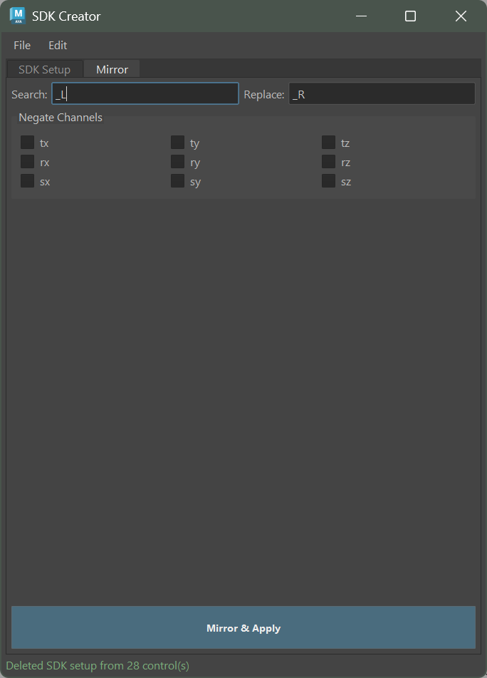
Search/Replace: Renames controls and UIHost (e.g.
_L→_R)Negate Channels: Flips the specified transform channels (tx, ty, tz, rx, ry, rz, sx, sy, sz) to achieve mirror behavior
Configuration
Save and load SDK setups using the File menu.
Export Config: Save the SDK setup to a
.sdkcfileExport Mirror Config: Export a mirrored version directly
Import Config: Load a
.sdkcfile into the UIApply from File: Apply an SDK setup directly from a file without loading the UI
The Edit menu provides Delete SDK Setup from Controls to cleanly remove SDK transforms and orphaned driver attributes.
Scripting Access
from mgear.rigbits.sdk_creator import core

# Apply from a saved config file
core.apply_from_file("/path/to/config.sdkc")

# Mirror an existing config
config = core.import_config("/path/to/config.sdkc")
mirrored = core.mirror_config(
    config, search="_L", replace="_R",
    negate_channels=["tx", "rz", "ry"],
)
core.apply_from_config(mirrored)